Strat® Install

Install guides and advice for your ObsidianWire Strat® harness
  • Easy. Not Instant.

    For a secure connection, take your time, and follow directions carefully.

Install Info:

Below you will find:

  • Layout Guide
  • Wiring Diagrams
  • Install Instructions
  • Demo Videos
  • Links to More Help
Download Manual
ObsidianWire Control hole layout / hole spacing diagram for Stratocaster

Will It Fit?

Layout Guide:

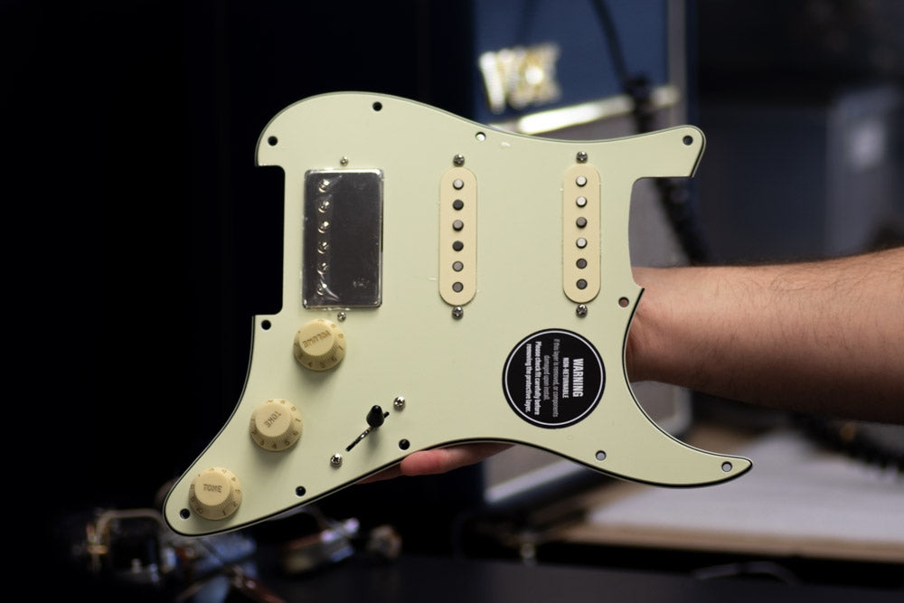
Fits most genuine Fender MIM and MIA Stratocasters

Fits most Squier and Fender Japan Strats // Requires hole size and knob adjustments (9.52mm Hole & 24 Spline Knobs) Push Pull loaded harnesses require full size cavity (min depth - 33mm)

Always Check Hole Layout

  • Hole Size: 9.52mm (3/8”)
  • Cavity Depth: Minimum 33mm (1.3”) (30mm depth required around push/pull pots)
  • Knob Size:  Use Split Shaft 24 Spline US SPEC ONLY
  • Switch Tip (Oak Type): Imperial / US Spec / Oak / CRL type
  • Switch Tip (Schaller Type - as used on Custom HSS // HSH) Schaller Tip

DOWNLOAD LAYOUT GUIDE

Wiring Diagrams:

Match your wiring diagram to your Pro-Wired Electronics model.

Check carefully.

Notes:

  • Slot 1 - Always Closest to Jack
  • Spare ground wires go to screw down connector
  • Ground all metal parts including tremolo / bridge and cavity sheilding

  • Blender 250k // Custom 7 G2 // Vintage G2

    1 = Spare Ground
    2 = Spare Ground
    3 = Output Jack Black
    4 = Output Jack White
    5 = Neck Ground
    6 = Neck Hot
    7 = Middle Ground
    8 = Middle Hot
    9 = Bridge Ground
    10 = Bridge Hot

    All other ground wires to screw down ground connector

  • Blender G2 // Universal Blender

    1 = Output Jack Black
    2 = Output Jack White
    3 = Neck Ground
    4 = Neck Hot
    5 = Neck Series 1
    6 = Neck Series 2
    7 = Middle Ground
    8 = Middle Hot
    9 = Middle Series 1
    10 = Middle Series 2
    11 = Bridge Ground
    12 = Bridge Hot
    13 = Bridge Series 1
    14 = Bridge Series 2

    All other ground wires - to screw down ground connector

    For two wires pickups - leave SERIES slots empty

  • CUSTOM HSS / HSH GEN2

    1 = Output Jack Black
    2 = Output Jack White
    3 = Neck Pickup Ground
    4 = Neck Pickup Hot
    5 = Neck Pickup Series 1
    6 = Neck Pickup Series 2
    7 = Middle Pickup Ground
    8 = Middle Pickup Hot
    9 = Bridge Pickup Ground
    10 = Bridge Pickup Hot
    11 = Bridge Pickup Series 1
    12 = Bridge Pickup Series 2

    All other ground wires to screw down ground connector

    Two Wire Bridge & Neck Pickups - Leave 'Series' slots empty

  • Lambertones HSS

    1 = Output Jack Black
    2 = Output Jack White
    3 = Neck Ground
    4 = Neck Hot
    5 = Middle Ground
    6 = Middle Hot
    7 = Bridge Ground
    8 = Bridge Hot
    9 = Bridge Series 1
    10 = Bridge Series 2

    All other ground wires to screw down ground connector

    Info Sheet
  • CUSTOM HH

    1 = Output Jack Black
    2 = Output Jack White
    3 = Neck Ground
    4 = Neck Hot
    5 = Neck Series 1
    6 = Neck Series 2
    7 = Bridge Ground
    8 = Bridge Hot
    9 = Bridge Series 1
    10 = Bridge Series 2

    All other ground wires to screw down ground connector

Install Instructions:

  •  

    1) Find Your Diagram

    • Find the correct diagram for your Strat® & Harness above.
    • Ensure the diagram is the correct one for the harness you are installing.
    Download Manual
  • Fender N4 noiseless pickup wire color codes
     

    2) Identify Your Pickup Wires

    • For most pickups:
      Hot = White
      Ground = Black
    • For different pickups you can check our pickup wire guide below

    Pickup Color Codes
  • 3) Cut Out Your Old Harness

    • Cut the pickup, and ground wires from your old harness, and remove it from your bass.
    • Cut as close to the old harness as possible to maintain the length of your wires.
  • 4) Prepare Your Wires

    • Strip pickup and ground wire insulation leaving 6mm (1/4”) of bare wire.
    • Be Precise
    • Twist loose strands of wire between your fingers to create a firm tip.
  •  

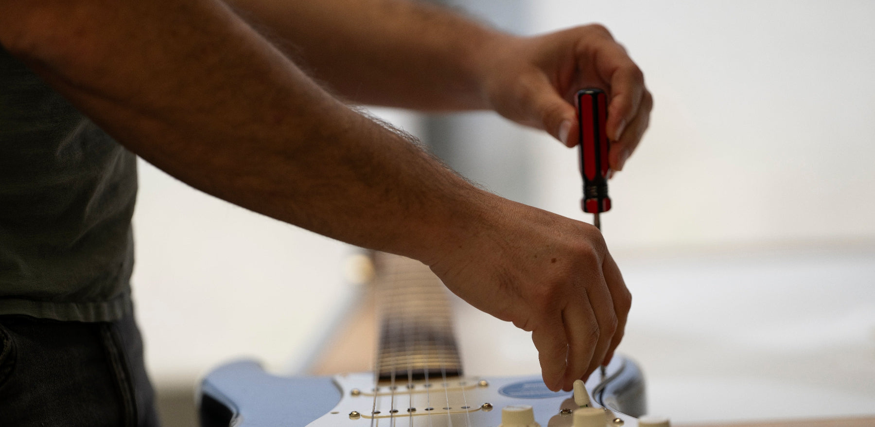
    5) Press & Hold Connector Button

    • Use a fine screw driver to press and hold the connector button above the wire slot.
    • For a full guide on using the solder-less connectors, check below
    Connector Guide
  • 6) Insert Wire & Release Button

    • Insert the wire to the correct slot at a 45° angle.
    • Release the button and the wire should hold firmly.
    • Test the wire by giving it a gentle pull before moving on to the next wire.

Install Videos:

The below demo videos are model specific. Always use the correct wiring diagram for your wiring model.

Custom Blender // Vintage

ST Custom HSS - Gen 1

More Help?